Withdrawal and Film Formation
The liquid is drawn away from the substrate and back toward the bath by draining forces. Entraining forces, on the other hand, aim to keep fluid on the substrate. The thickness of the wet film deposited onto the substrate is determined by the balance between these two sets of forces. There are four distinct areas in which the wet film forms during the withdrawal stage (shown in Figure 1).
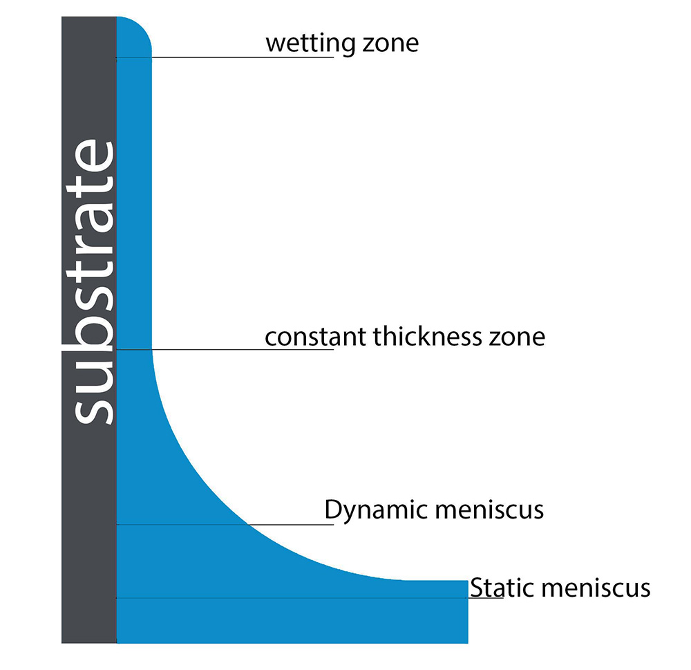
Fig. 1. Four different areas are involved in the development of the dip coating layer. These are the wetting zone, the constant-thickness zone, the static meniscus, and the dynamic meniscus.
These four regions are:
- The hydrostatic and capillary pressures are balanced in the static meniscus, which gives the meniscus its form.
- Around the stagnation point, there is a dynamic meniscus. The balance between the entraining forces and draining forces is known as the stagnation point.
- When the wet film has attained a specific thickness, it is known as the constant-thickness zone (h0).
- The area where the wet film first appears is known as the wetting zone.
The solution flow in this area and the dynamic meniscus control the wet film thickness.
Within the boundary layer, the meniscus changes from static to dynamic (L). The solution travels in this area under the influence of viscous flow forces. The draining forces are substantially stronger than the viscous forces outside of the boundary layer. The meniscus in this area is determined by the equilibrium between the hydrostatic and capillary pressure.
When both the entraining and draining forces are equally balanced, the stagnation point is reached. The balance of these forces decides how thick the film will be. The viscous flow, draining, and capillary regimes are the three main coating regimes, each of which is identified by the forces that predominate in the behavior of the coating.
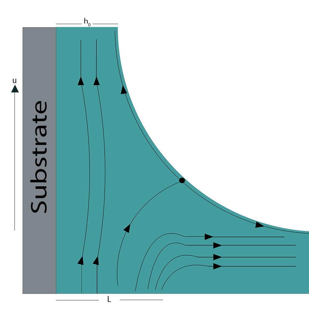
Fig. 2. The harmony of entraining and draining forces controls the flow of the solution. The entraining forces start to affect solution flow at the dynamic meniscus and eventually overtake it.
Viscous Flow and Drainage Regime
The viscous flow phase is the initial coating regime. High speeds and viscous liquids cause this to happen. Here, gravitational attraction and viscous forces dominate the coating. Equation 1 may be used to determine the liquid layer’s thickness in this situation.
![\[ {h_0=c{\left(\frac{{\eta U}_0}{\rho g}\right)}^{\frac{1}{2}}} \]](https://quicklatex.com/cache3/21/ql_d1e8c08c4b45323593be26588f12cf21_l3.png "Rendered by QuickLaTeX.com")
Eq. 1. The formula for determining the wet film thickness for dip coating in the domain of viscous flow.
This is determined by the viscosity (η) and the substrate’s rate of withdrawal from the solution (U0). The draining force is gravity, which is determined by the gravitational constant (g) and the density of the solution (ρ). The dynamic meniscus’s curvature is related to the constant (c). The rheological characteristics of the solution are closely tied to this constant, which is a feature of the solution itself. This constant, for the majority of Newtonian liquids, is about 0.8.
The majority of the time, the withdrawal rates or solution viscosities won’t be high enough for this approximation to hold true. The viscous force weakens when these two factors are decreased. Therefore, surface-tension-driven movement of the solution is also necessary to maintain a balance between the entraining forces and the draining forces. The coating is considered to be inside the drainage regime when these circumstances exist. Equation 2 provides a description of the connection between the wet film thickness and substrate pullout speed using the Landau-Levich equation (when surface tension is considered).
![\[ {h_0=c\frac{{\left(\eta U_0\right)}^{\frac{2}{3}}}{{{\gamma }^{\frac{1}{6}}}_{LV}{\left(\rho g\right)}^{\frac{1}{2}}}} \]](https://quicklatex.com/cache3/48/ql_d7f5cc371f3d62f3f908d76f848fd648_l3.png "Rendered by QuickLaTeX.com")
Eq. 2. The viscous flow equation has been adjusted to include the surface-tension-driven flow in the Landau-Levich equation.
Up until very low withdrawal speeds, the Landau-Levich equation is valid. The third phase of the coating takes place when the speed is lowered to less than around 0.1mm/s. The capillary regime is the name given to this system. In the capillary regime, evaporation occurs at a faster pace than the solution is entrained onto the substrate (via viscous flow). Therefore, understanding the capillary regime requires a grasp of drying dynamics.
Drying Dynamics
Three distinct drying phases are commonly included in dip coating:
- Front drying while coating
- The era of constant rate
- The era of declining rates
The constant rate period and the dropping rate period are the two basic drying stages. Within the constant-thickness zone is where the constant rate period takes place (during and after coating). Here, solvent evaporation takes place uniformly over the wet film’s surfaces. This only differs at the substrate’s margins, where the drying front appears.
The wet film will gradually lose the majority of its solvent until a gel-like film is created. The phase of declining rates starts at this time. The little solvent that is left is held inside the gel during the time of declining rate, and the evaporation is controlled by the solvent’s diffusion to the surface.
The dryer front is where the more difficult drying step takes place (shown in Figure 3). The wetting zone is where the drying front is most visible since it is where the wet film and substrate meet. Here, evaporation happens significantly more quickly due to the increased surface-area-to-volume ratio, resulting in the creation of a wet film with a higher concentration. As a result of surface-tension-driven phenomena, the solution is drawn from the surroundings. A capillary force will be applied to the solution once the dry film has formed on the solution at the drying front. As a result, the solution thickens the deposited film by being wicked into the dry layer.
During the capillary regime of coating, the solution is sucked into the drying film (due to the capillary force). The pace at which the drying front retreats is much slower than the rate at which the constant-thickness zone forms at fast enough withdrawal speeds. As a result, the constant rate period dominates the drying dynamics, and the ultimate film thickness depends on the starting wet film thickness. The drying front dominates the drying dynamics at slow withdrawal rates (where the drying front retreats more quickly than the rate of withdrawal).
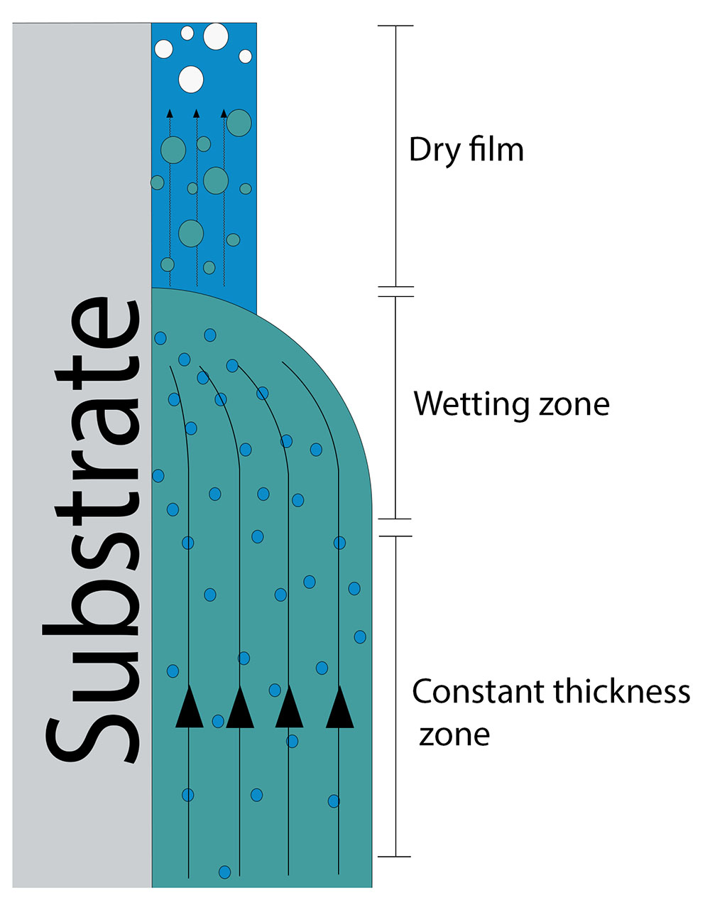
Fig. 3. The development of a concentration gradient and the capillary action of the dry film govern the dynamics of drying in dip coating.
Capillary Regime
The thickness of the wet film is not taken into account in the capillary regime. This is due to the fact that at these coating speeds, a constant-thickness zone is never actually attained. The ultimate thickness in the capillary regime thus depends on the rate of withdrawal, the characteristics of the solution, and the solvent’s rate of evaporation. Equation 3 consequently provides the dry film thickness.
![\[ {h_f=k\frac{E}{LU_0}.k=\frac{cM}{\alpha \rho }} \]](https://quicklatex.com/cache3/56/ql_1a74bf728529b8b697f063f7b8f1b656_l3.png "Rendered by QuickLaTeX.com")
Eq. 3. The speed and rate of solvent evaporation are also factors in the capillary flow equation. The dry film characteristics are determined by a constant (k) known as the “materials proportion constant.
Here, the ultimate dry film thickness is determined by the evaporation rate (E), coated film width (L), withdrawal rate (U0), and materials percentage constant (K) (hf). K combines the characteristics of a solute, solution, and dry film. The constant is caused by the solute’s total concentration in solution (c), molar weight (M), density (ρ), and porosity (α) of the film that was deposited.
The molecular weight of the substance, the concentration, and the density of the solute all have a direct and straightforward effect on the dry film thickness. The porosity value is somewhat more complicated, though. The porosity affects the kinetics of drying in addition to varying the density of the film in relation to the raw material. As previously explained, at the drying front, where the wet film and the dry film come into contact, the wet film will be pulled into the dry film by capillary action. The film’s porosity has a significant impact on this as well, dictating how quickly and how far the solution will penetrate the dry film as well as how quickly the absorbed material will dry.
Film Thickness vs. Withdrawal Speed
It is necessary to apply both the Landau-Levich equation and the capillary regime equation to determine the dry film thickness as a function of withdrawal speed. A sample removal speed vs. film thickness graph for the dip coating process is shown in Figure 4. During the transition between these two coating regimes, a minimum coating thickness for dip coating is attained. The various coating regimes take control when the withdrawal speed moves away from the minimum in either direction.
The thickness curve may be determined at both high and low speeds using the Landau-Levich equation or only the capillary regime equation. However, neither equation by itself can provide precise values for the coating thickness across a wide range of coating rates. When the coating thickness is at its bare minimum, something happens. You need an equation that combines the Landau-Levich equation with the capillary regime equation to get the minimal thickness. The following part will go through this.
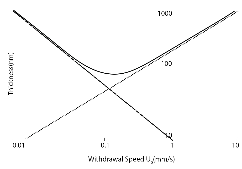
Fig. 4. The film thickness may be calculated using either the Landau-Levich equation or the capillary regime equation. Both equations must be considered at the intersection of the two zones.
Minimum Film Thickness Equations
The equations determining the thickness under the drainage regime and the capillary regime must be coupled in order to establish the minimal thickness. In order to connect the wet film thickness to the dry film thickness, Equation 2 must first be modified. Simply adding the “materials percentage” constant to the calculation will do this.
Equation 4 is produced by adding the two equations. Here, Equation 3’s capillary regime is represented by the first term in the bracket, while Equation 4’s drainage regime is represented by the second term (Equation 2). A universal solution constant has been created from the constants in Equation 2 (D).
![\[ {h_f=k\left(\frac{E}{{LU}_0}+D{U_0}^{\frac{2}{3}}\right)} \]](https://quicklatex.com/cache3/29/ql_f7e908f72169dce519506274e9998329_l3.png "Rendered by QuickLaTeX.com")
Eq. 4. The contribution from the capillary and drainage regimes is included in the equation for film thickness, which provides information on the ultimate dry film thickness.
The lowest film thickness may be calculated using this equation by separating the thickness in relation to the withdrawal rate. Equation 5 is obtained by setting this derivative to 0 (which is the gradient at the minimum’s inflection point).
![\[ {U_{min}={\left(\frac{2DL}{3E}\right)}^{-\frac{3}{5}}} \]](https://quicklatex.com/cache3/28/ql_2bfb6cc728aba761c6871a8833ebd928_l3.png "Rendered by QuickLaTeX.com")
Eq. 5. By using the differential of the thickness equation to calculate when the slope of the graph becomes zero, it is possible to determine the minimum thickness for dip coating.
There are a number of contributing elements that have not been taken into account, despite the fact that this equation provides a near approximation to the actual film thickness attained. These include Marangoni flow, heat gradients, surface air flow, varying evaporation rates, viscosity and concentration gradients, and other variables that can change over time.
Changing Withdrawal Speed
There are two primary factors that characterize the meniscus:
- Based on the gravitational viscous drag
- Surface interactions between the solution and the substrate
The meniscus solution will either drop back into the reservoir or be drawn up with the substrate to form a film, as seen in Figure 5. At the drying line, the meniscus comes to an end. At this stage, a solid film has formed after the solvent has completely evaporated or been drained. The drying line advances at the same pace as the speed of the withdrawal. The meniscus remains close to the substrate-reservoir border as the substrate is removed, thus “moving down” the substrate. The capillary area (low speed) and the draining region are the two primary dip coating regions separated by withdrawal speed (high speed).
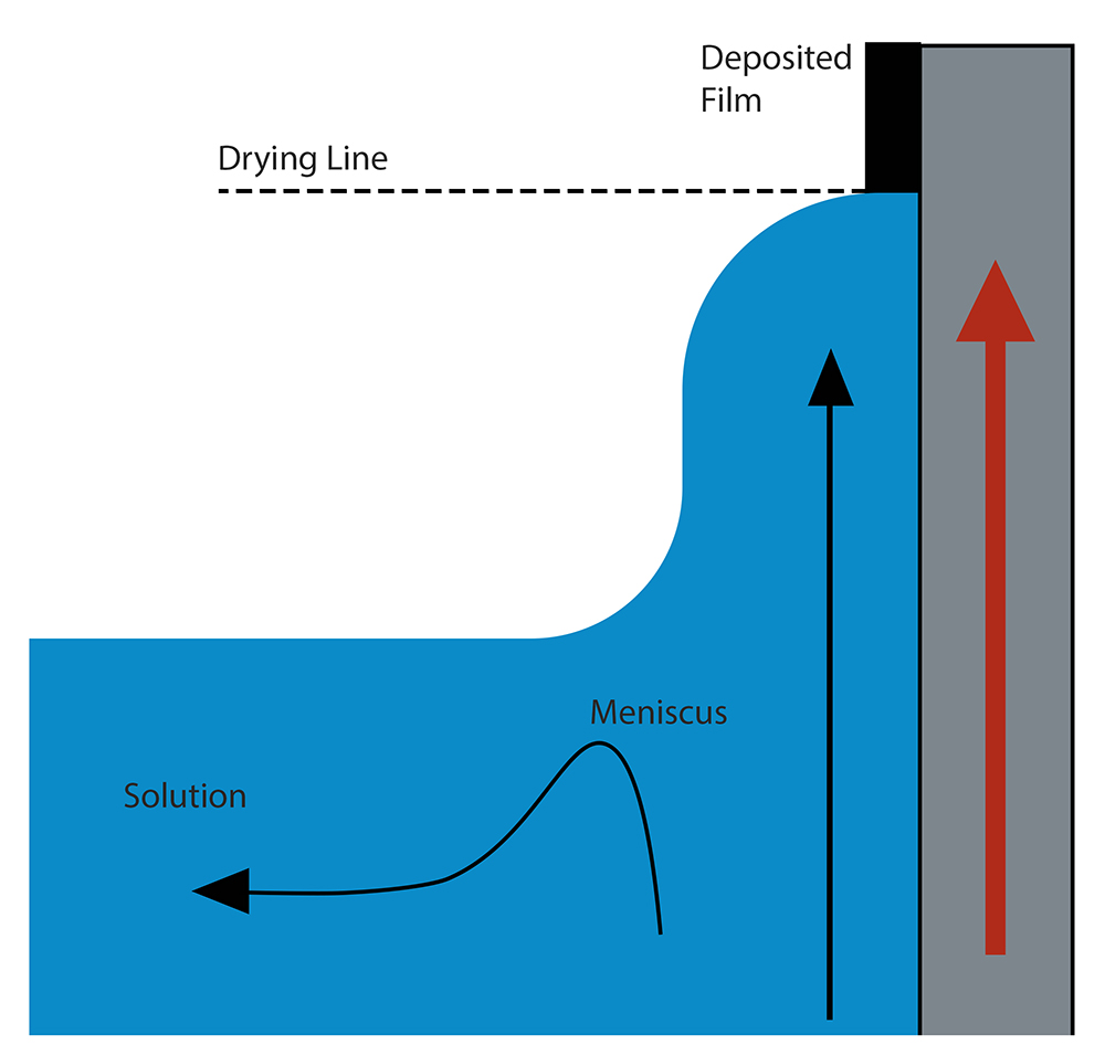
Fig. 5. As the substrate is pulled out, the liquid is either dragged up with the substrate by surface forces or falls back into the reservoir as a result of gravity forces.
Withdrawal rates in the draining area exceed 1 mm/s. The solvent is evaporating less quickly than the drying line is moving. According to the Landau-Levich model, in this case, the ink characteristics and the withdrawal speed control the film thickness. The rate of evaporation plays a little role in this.
Withdrawal rates in the capillary area are typically lower than 0.1mm/s. The crucial element in this situation is that the evaporation rate is higher than the drying line’s “movement.” The solvent evaporates in this instance as soon as the ink is introduced into the top portion of the meniscus. As additional ink is pulled up the substrate by surface forces, it is then replaced, and once again, the solvent evaporates. Capillary feeding occurs here. As a result, the film in this area is thicker the slower the withdrawal pace is.
A mixture of the aforementioned models can correctly represent the area between these two. The thinnest film is created in this region, which is depicted in Figure 6 as having a V-shaped dependence on withdrawal speed. Work with faster withdrawal rates if at all feasible because working in the capillary zone can lead to some of the problems described in this guide. To obtain a homogeneous coating, nevertheless, it could be required to utilize modest withdrawal speeds if the coating ink is extremely diluted.
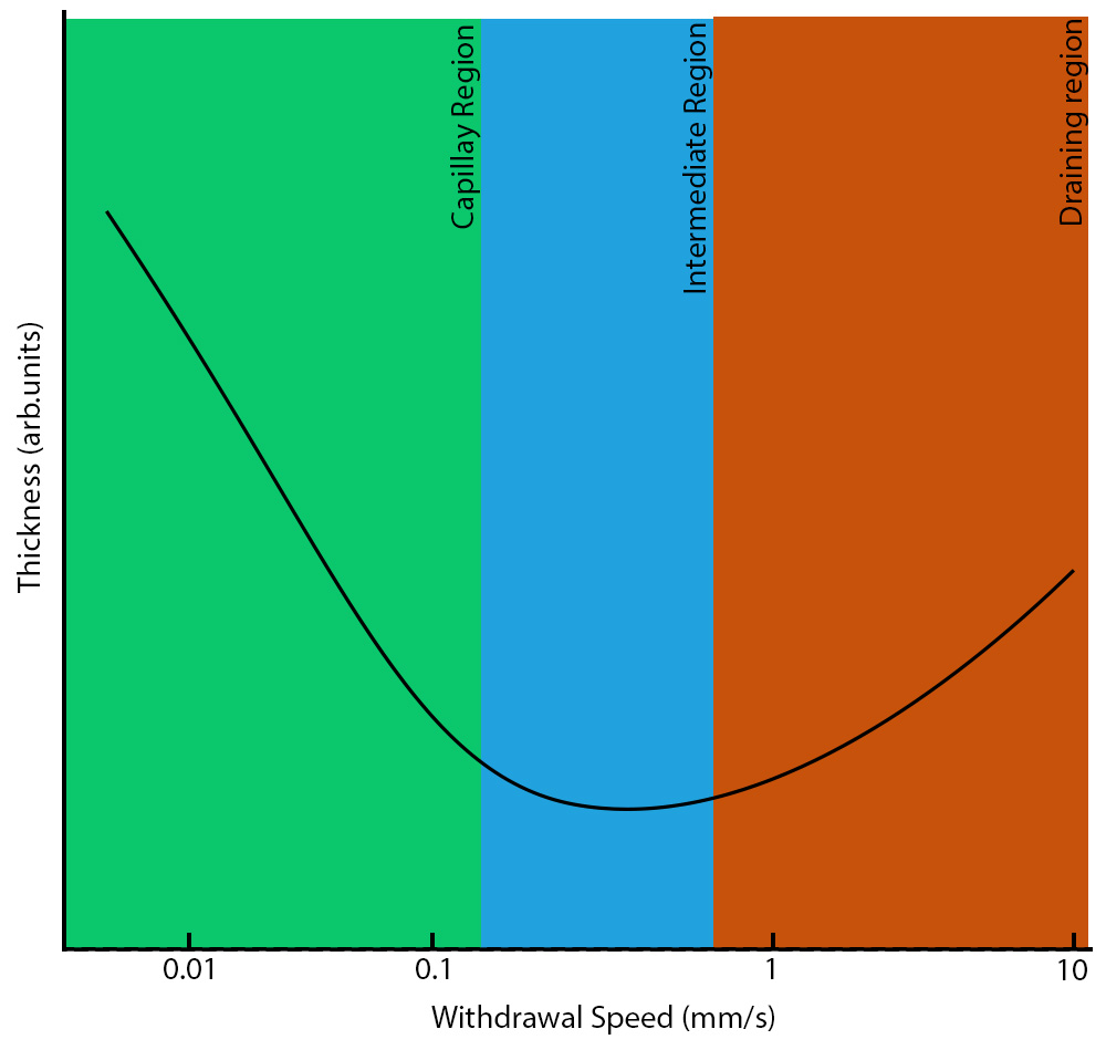
Fig. 6. Changes in film thickness are dependent on withdrawal speed. The graph only displays a broad trend; hence the units are arbitrary. The real film thickness might be influenced by other elements, such as liquid viscosity.
Wet Thin Film Coating
By initially creating a wet layer that is almost atomically thin, wet thin film coating methods employ a liquid precursor to coat a substance uniformly across the surface of a substrate. Wet thin film coating is less costly and creates high-quality films with comparable ease when compared to other deposition techniques. It is, therefore, a good candidate for investigation.
All the information you need to get started is provided in the written guides, application notes, and videos on this page that cover wet thin film coating from both a theoretical and practical standpoint. The advice provided here will help you hone your method, eliminate frequent flaws and hazards, and increase the repeatability of your studies if you are already familiar with the wet thin film coating.
Continue to the 3rd Part of the Note
Review the 1st Part of the Note