Based on the two primary factors that dip coating is susceptible to, there are two basic kinds of dip coating defects. These groups include:
- Defects brought about by dip coater instability or a change in withdrawal speed.
- Defects brought on by “external” elements like the environment the substrate is covered in or the viscoelastic and chemical characteristics of the ink.
When dip coating thin films, a variety of techniques can be employed to avoid flaws. The frequent issues and flaws are covered in the section that follows, along with the distinguishing traits that may be used to recognize them, their causes (and sources), and solutions. When investigating flaws, the following should be kept in mind:
- Frequency of the defects
- Where the defects occur
- When in the coating process, they occur
- Defect size and shape
This knowledge makes it simple to find, recognize, and fix a fault. Users may start producing consistent, high-quality films utilizing the dip coating technique once all parameters have been taken note of and optimized.
Stripe Defects
An example of this is depicted in Figure 1. This flaw can be seen along the covered substrate at regular intervals. Stripes have the following characteristics:
- Bands of thicker film that run parallel to the direction of withdrawal and form horizontal stripes.
- The film thickness may show as a color variation or structural inhomogeneity.
- The flaw will manifest itself at nearly equal intervals or frequency.
This dip coating problem is typically caused by a slow withdrawal rate.
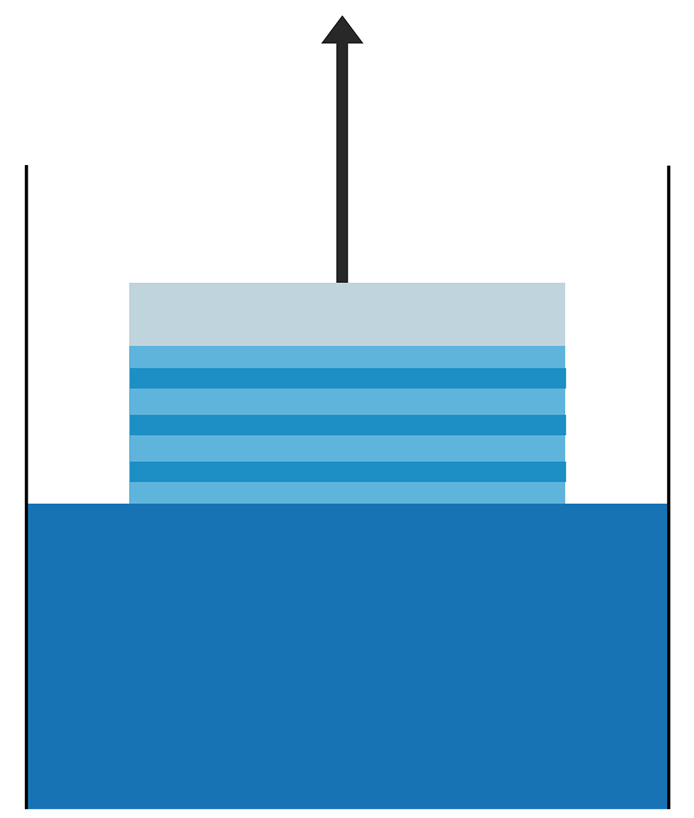
Fig. 1. Horizontal lines after withdrawal.
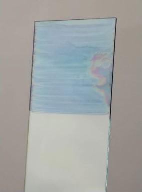
Fig. 2. When a substrate is dip coated while the withdrawal speed is slow, the film develops horizontal stripes.
Low Withdrawal Speeds
The “coffee-ring effect” can cause special flaws in films made in the capillary area. Evaporation rates are high when ambient temperatures are high. The solute is left behind as the solvent near the meniscus’s edge first evaporates. As soon as the solvent has evaporated due to capillary feeding, new ink takes its place. As a result, the edge is “pinned” here (see Figure 3).
As a result, more solute is deposited along the meniscus’s edge, which causes the film to be thicker there. This pinned edge separates from the meniscus as the substrate is raised. The meniscus descends till the edge is once more fixed. Since this process will keep happening repeatedly, these “stripes” will be regular.
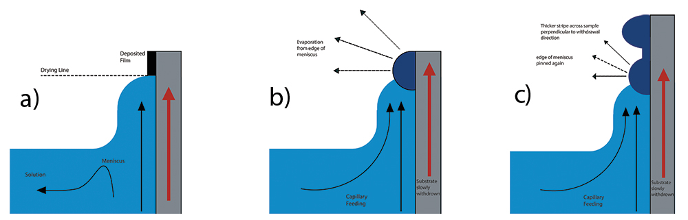
Fig. 3. a) Film is deposited at the meniscus’s edge and is influenced by the characteristics of the liquid and its rate of withdrawal. b) More material is deposited at this meniscus edge when the rate of evaporation is high. c) As a result, the substrate is covered with thicker ridges. Another meniscus forms as the substrate is still being removed, pinning the edge once again.
Increasing withdrawal speed or lowering ambient temperature are the two methods for reducing this impact. Both zones are capable of producing thick coatings, but the capillary region is the only one where these “coffee-ring” effects are visible. You eliminate this issue by quickening withdrawals. Withdrawal rates greater than 1mm/s are advised to enter the draining area. This may also need raising the concentration if your ink is extremely dilute in order to obtain consistent coverage on your film. It should be noted that the rate of withdrawal has an upper bound.
If you can’t alter the concentration, you may also lower the temperature to decrease this impact. Temperature reduction lessens capillary feeding because it slows evaporation. However, this may still result in the film’s inhomogeneity, which would show as a color fluctuation. To further slow down the solvent’s evaporation, another option is to employ a different solvent (in which the solute is dissolved) with a higher boiling point.
Visible Particles, Pinholes, and Craters
The microstructure of the film’s obvious flaws is covered in this section. Visible markings, pinholes, and craters are the three basic forms of flaws. Figure Whatever serves as an illustration of these consequences. Figure 4 illustrates how these two vary. There are a number of indications that a film may have flaws, including:
- Visible particles on the film’s surface.
- The optical properties of the film could be affected.
There are several potential causes of these flaws, including:
- Dust or contamination on the substrate before coating
- Aggregation or crystallization of the solute
- Evaporation cooling effects
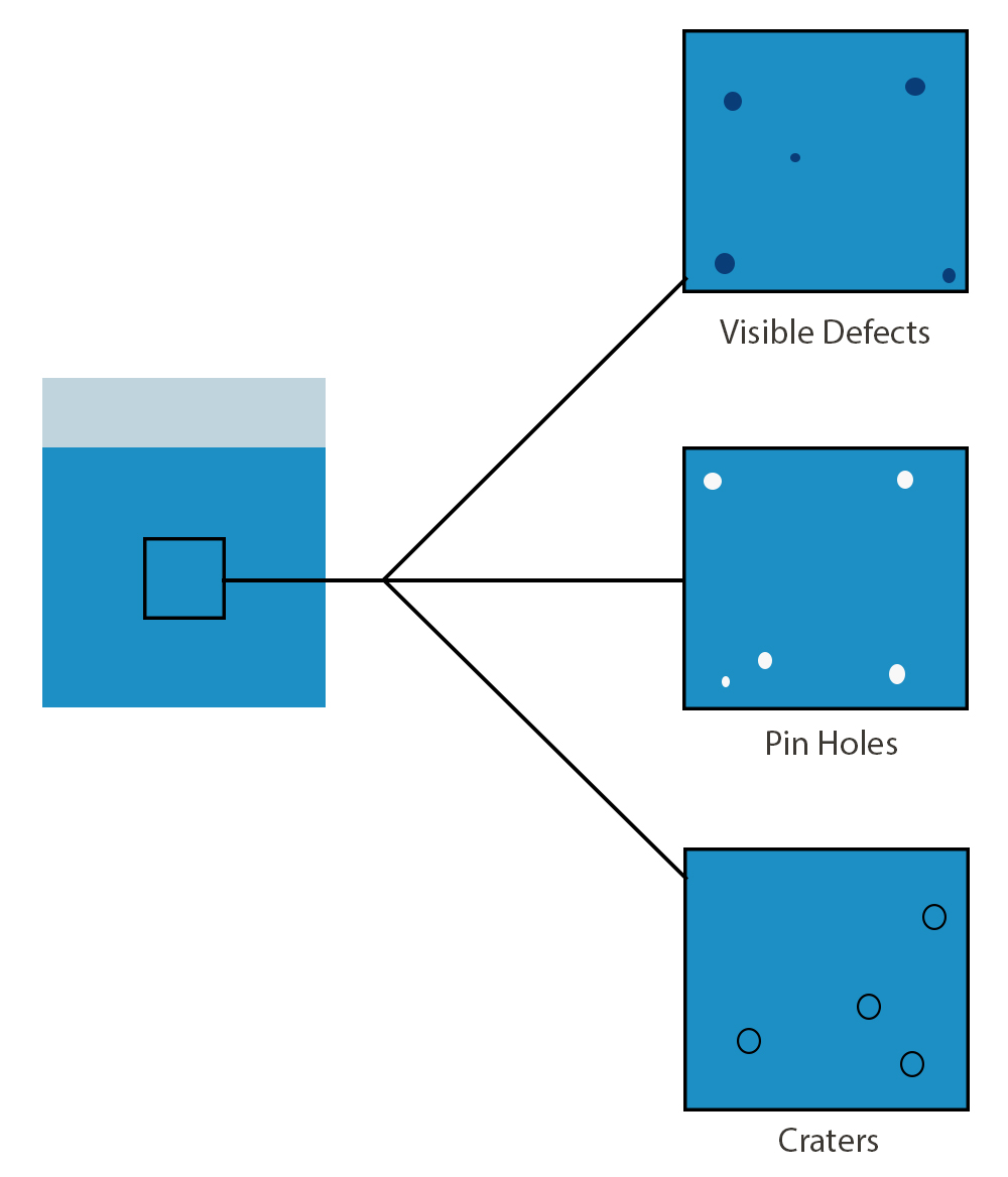
Fig. 4. Defects that can occur on the microscale of film during dip coating
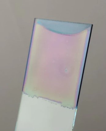
Fig. 5. When a substrate is polluted before being coated, comets and other flaws are left in the film.
Dust or contamination on the substrate before coating
Defects in the film may be caused by the existence of tiny particles, which are frequently apparent. Either the particles serve as sites of aggregation, or the solution leaves comet-like trails in its wake. This contamination might still result in pinholes even if the tiny particles are taken out before the film is applied. A pinhole can be formed if the film is thinner due to inadequate wetting caused by previous contamination, which can alter the surface energy of a substrate.
So, before deposition, the substrate needs to be well-cleaned. A comparable procedure to that used for spin coating is needed to clean substrates for dip coating. The substrate should first be thoroughly cleaned with an electronic-grade cleaner (like Hellmanex III) and a semi-polar solvent (like acetone/IPA). By doing this, the substrate is made sure to be free of any dust or other residues. Second, it is helpful to chemically prepare a substrate before coating it in order to expose active “-OH” terminations that will facilitate efficient wetting. This entails washing it with a NaOH solution or a UV Ozone/oxygen plasma cleaner. The substrate must subsequently be kept in a sanitized setting for storage in order to prevent additional contamination.
Aggregation in Solution
The solute may have aggregated or crystallized, depending on the inks employed. Materials that are only moderately soluble in the utilized solvent experience this. Additionally, during the dip coating process, solutes may clump or crystallize rather than produce an even layer.
If crystallization took place prior to deposition, heating the ink might be able to re-dissolve it. In order to remove any contamination, inks should always be filtered before usage. To minimize any apparent contamination, the pore size utilized in the filtering should be nearly equal to the film thickness. Pore diameters of about 2µm are advised, while smaller ones may be employed under certain circumstances. The inks often need to be filtered if they are being kept.
Evaporation Cooling Effects
During the drying step, solvent evaporation cools both the substrate and the film. The crater-like imprints this cooling might leave in the film’s fine structure during later film creation could cause a number of issues. This may result in a hazy coating when there ought to be a transparent one on a large scale (as shown in Figure 6).
![]()
Fig. 6. There may be flaws in the film if clear coatings (left) seem translucent (right).
By heating the ink before deposition, this impact can be minimized. Even a small amount of heating, up to 25°C, may significantly improve film uniformity. Additionally, it’s crucial to immerse the substrate in the ink for 30 to 60 seconds. It can then achieve thermal equilibrium with the ink as a result. The substrate may then store this heat during withdrawal, lessening the impact of evaporative cooling even further.
Partial or Inhomogeneous Coating of the Substrate
The following traits of an inhomogeneous film are present:
- Color variation appears across the coated substrate
- Thickness variation occurs across the film

Fig. 7. Examples of inhomogeneity in films.
Inhomogeneity’s cause might be one of the following:
- Insufficient Wetting
- Meniscus Height Issues
- Turbulent Airflow During Drying
- Inconsistent Withdrawal Speed
Insufficient Wetting
Contact angle analysis is one method for determining an ink’s wettability (whether it will spread across a substrate). A liquid has a high degree of substrate wettability if the contact angle is modest. It will, therefore, effectively spread (see Figure 8).

Fig. 8. The relationship between contact angle and wettability.
The surface tension of the liquid and the surface energy of the substrate are two factors that affect contact angle. The molecules will have a strong attraction to one another if the liquid’s surface tension is high, which leads to dewetting. However, if the surface energy is large, wetting will occur because the liquid molecules’ attraction to the substrate will be stronger.
The ink won’t adequately cover the substrate if either the surface energy of the substrate is too low or the surface tension of the ink is too high. A balance between gravitational-based “draining” forces and surface-tension-based “capillary” forces results in the meniscus that forms during dip coating. It will be difficult to produce a homogeneous coating of the substrate if the ink is more attracted to itself than it is to the substrate in the first place.
It is frequently preferable in this circumstance to switch to a solvent with lower surface tension, employ a surfactant, or modify the substrate to boost its surface energy (i.e., with an oxygen plasma). For organic-based transistors, where low surface energy is required for maximum performance, the latter is not advised.
Turbulent Airflow During Drying
The wet film is quite susceptible to outside influences during the drying process, notably airflow. Inhomogeneities can result from evaporation and drying rates that are impacted by turbulent airflow. Inadequate airflow over the surfaces might also result in drying issues. The inhomogeneity will not display a clear pattern but instead may create “streaks” of thicker or thinner material.
The substrate should ideally be dried in a laminar flow environment that is continuous so that variables like evaporation rates may be controlled. However, care must be taken since airflow can bring about contamination, and the film is particularly susceptible to this during the drying process. This stage must be completed in a spotless setting, such as a clean room.
Inconsistent Withdrawal Speed
Film thicknesses produced during dip coating are influenced by the pullout speed. As a result, if the withdrawal speed is inconsistent, the film’s thickness will vary. If this occurs, the thicknesses would only change perpendicular to the direction of withdrawal. Consistent thicknesses would be seen along the substrate (perpendicular to the direction of withdrawal). Figure 9 gives an illustration of this.

Fig. 9. An illustration of an inhomogeneous dip-coated film. Here, a color difference corresponds to a change in substrate thickness. As the withdrawal speed varies, thickness fluctuation may be noticed perpendicular to the withdrawal direction.
Meniscus Height Issues
Film thickness is evaporation rate-dependent at low withdrawal speeds. This, in turn, depends on the surrounding environment of the film. The meniscus may rise over the reservoir as the substrate is submerged and if the reservoir is overflowing.
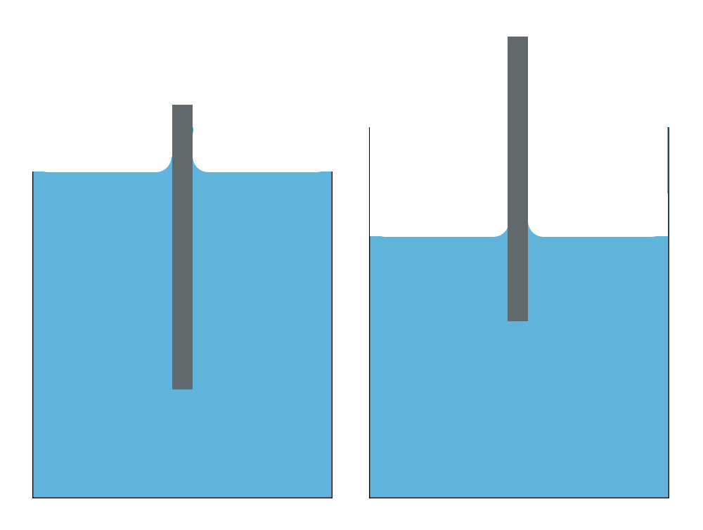
Fig. 10. The meniscus height can vary dramatically as the substrate is submerged. The meniscus is exposed to two distinct environments in these two images, one within the reservoir and one above it.
Evaporation occurs with an extremely slow withdrawal velocity near the meniscus edge. Effectively, the reservoir’s atmosphere and the atmosphere above it expose this meniscus to two separate environments. This can result in various evaporation rates and, thus, various film thicknesses. The mistake is presumably present if a thickness profile displays a peak in thickness at the beginning of film creation (see Figure 11). It is crucial to make sure that the depth of the solution stays largely consistent in order to minimize this impact. As a result, the solution’s volume must be much bigger than the substrate’s.

Fig. 11. A dip-coated, inhomogeneous film is produced. Here, a color difference corresponds to a change in substrate thickness. The initial deposition is where the biggest discrepancy exists. The substrate is now most thoroughly covered with ink.
Cracking
After post-deposition heat treatment, a thin layer frequently exhibits cracks. Cracking in thin films is covered in this section. These cracking features are:
- Long, straight cracks on the microscale of film structure
- The amount of cracking will increase with film thickness
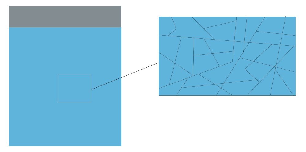
Fig. 12. Microscale cracks can develop in these films as a result of the post-deposition treatment required while dip coating, which occurs often.
The causes of this defect could be:
- Small particles on the film surface
- Loss of water/organics during deposition
- Thermal expansion mismatch
Small Particles on the Film Surface
Contamination during the “wet” stages is a major factor in the breaking of thin films. These will produce structurally-weak areas weak areas and may subject the film to additional stress during heat treatment. As previously stated, films should be developed in a clean setting, ideally with laminar, pure airflow. It should be mentioned that if the film thickness is over the critical thickness, the resulting cracks are much more serious.
Loss of Water/Organics in Film
There is a significant volume shift from the original liquid layer to a solid layer during dip coating. As a result of the film’s viscoelastic relaxation during heat treatment this might result in the development of large fissures. If the film is thicker than the critical thickness, these impacts can be seen. For instance, if the film is thicker than the essential thickness and minute particles contaminate it during the early drying step, major fractures will develop. Experimental research may be used to determine the critical thickness, which varies for every ink.
Thermal Expansion Mismatch
If the substrate and ink have thermal expansion coefficients that are significantly different, cracks may occur. The bonds tying them together are put under stress since the substrate won’t expand or contract at the same rate as the film. These ties may rupture as a result of this. It is crucial to choose a substrate with a thermal expansion coefficient that is comparable to the ink’s (where possible).
All these problems are dependent on film thickness. In general, the thicker the film, the more cracks will appear. Where possible, it is advantageous to have thinner films. However, if thicker layers are needed, it may be beneficial to apply multiple thin layers with annealing after each one. It must be noted that applying multiple layers may affect the microstructure of the overall film.
Running (Curtaining)
The ink may be observed to flow when the deposition process dries off. This running, sometimes known as “curtaining,” is frequently attributed to the lengthy drying durations brought on by thick wet films. The film thickness rises with the withdrawal speed during the drainage cycle. Thick films will require more time to dry since there is more solvent present in them. An uneven film distribution might result from the deposited ink starting to flow before it dries, which is more likely to happen with the longer drying period.
This would typically occur at speeds of about 15 mm/s and with viscous fluids. The likelihood of the wet film running during the drying process can be decreased by adjusting the solution’s viscosity. Increasing the rate at which the film dries after the formation of the coating is another way to reduce running. To achieve this, use an annealing chamber to quickly dry the film.
Review the 2nd Part of the Note